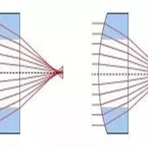
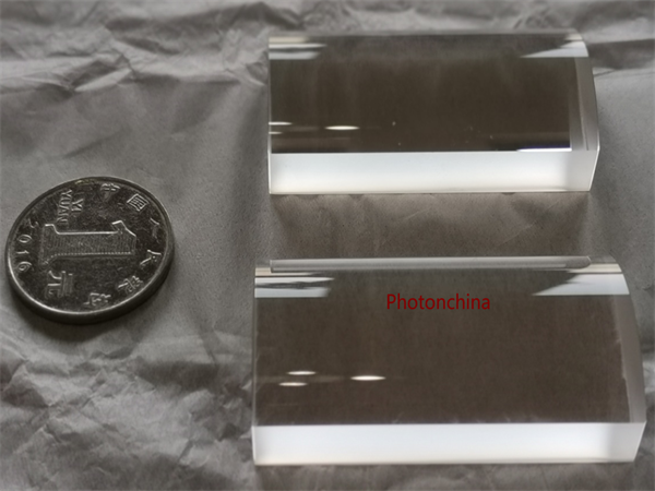
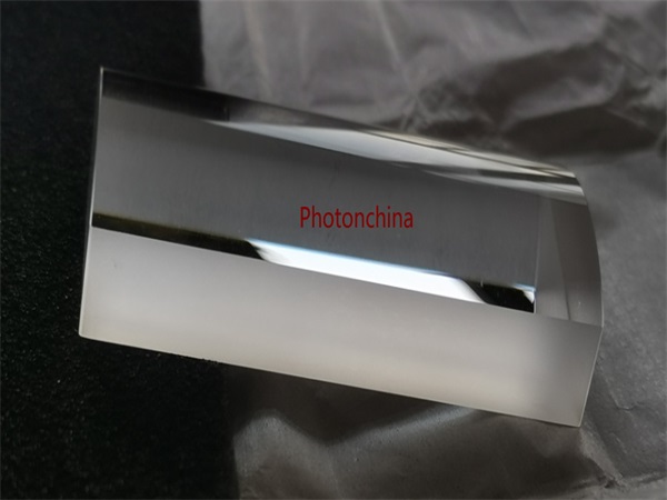
Acylindrical lenses, Aspherical cylindrical lenses, or acylinder lenses, are the cylindrical counterpart to an aspheric lens and designed to combine the aberration-reducing benefits of an aspheric surface with the one-dimensional focusing of a standard cylindrical lens.
Positive cylindrical lenses are ideal for uses requiring magnification in one dimension. While spherical lenses work symmetrically in two dimensions on an incident ray, cylindrical lenses act in the same manner but only in one dimension. A typical application is to use a pair of cylindrical lenses to provide anamorphic shaping of a beam. A pair of positive cylindrical lenses can be used to collimate and circularize the output of a laser diode. Another application would be to use a single lens to focus a diverging beam onto a detector array.
Photonchina’s cylindrical lenses are slightly deviated from a true cylinder in a way that minimizes the introduction of aberrations, which result in a wavefront error of 500nm.One of our lenses is fabricated using S-LAH64 optical glass, that is a low dispersion glass with high index of refraction in order to limit chromatic aberration.
Features:
Cylindrical lenses featuring an aberration-reducing acylindrical surface
Numerical apertures:0.45-0.50
Optical Coating: A:350 – 700 nm, B:650 – 1050 nm C: others specified by customers
Photonchina Specifications |
|
| Design Wavelength | 780 nm or others |
| AR Coating Range | 350 – 700 nm (-A Coating) 650 – 1050 nm (-B Coating)Others could be specified by customer |
| RMS Wavefront Error | < 0.5 µm |
| Surface Quality | 60-40 or better |
| Lens Material | S-LAH64 or other materials |
| Index of Refraction at 780 nm | 1.777 |
| Abbe Number | 47.3 |
Order information
| Item # | FL (mm) |
Size (mm) |
CT (mm) |
ET (mm) |
CA (Collimation) (mm) |
CA (Focusing) (mm) |
NA | WD (mm) |
| ACL8 | 8.0 | 10.0 x 10.0 | 3.03 | 0.9 | 9.0 x 9.0 | 9.0 x 8.1 | 0.49 | 6.3 |
| ACL10 | 10.0 | 12.5 x 12.5 | 5.0 | 1.6 | 11.25 x 11.25 | 11.25 x 9.4 | 0.49 | 7.2 |
| ACL12 | 12.0 | 15.0 x 15.0 | 5.0 | 1.8 | 13.5 x 13.5 | 13.5 x 11.9 | 0.49 | 9.2 |
| ACL15 | 15.0 | 18.0 x 18.0 | 6.0 | 2.3 | 16.5 x 16.5 | 16.5 x 14.6 | 0.48 | 11.6 |
| ACL18 | 18.0 | 20.0 x 20.0 | 6.5 | 2.8 | 18.0 x 18.0 | 18.0 x 16.0 | 0.45 | 14.3 |
| ACL20 | 20.0 | 25.0 x 25.0 | 7.5 | 2.2 | 22.5 x 22.5 | 22.5 x 20.4 | 0.49 | 15.8 |
| ACL26 | 26.0 | 30.0 x 30.0 | 8.0 | 2.2 | 28.0 x 28.0 | 28.0 x 26.2 | 0.47 | 21.5 |
| ACL32 | 32.0 | 45.0 x 45.0 | 13.0 | 2.1 | 41.0 x 41.0 | 41.0 x 38.0 | 0.54 | 24.7 |
| AYL40 | 40.0 | 50.0 x 50.0 | 14.0 | 3.4 | 46.0 x 46.0 | 46.0 x 42.7 | 0.50 | 32.1 |
Focal lengths tolerance:<1%
Note: Materials like Fused Silica (JGS1) or others are available according to customers request.
Considerations suggested when buying cylindrical or acylindrical Lenses.
Errors and Aberrations.
Misalignment during the grinding and polishing process could lead to a few mechanical errors specific to cylinder or acylinder lenses that can cause optical aberrations and negatively impact performance.
No manufacturing process of cylinder or acylinder lenses is free of imperfections, which makes small amounts of geometric errors unavoidable. Therefore, these errors must be tightly controlled to make sure of the performance of the lens. These errors are defined regarding geometric datums including the planar side of the lens and the edges of the lens.
Wedge
In an ideal cylinder, the planar side of the lens is parallel to the cylinder axis. Angular deviation between the planar side of the lens and the cylinder axis is known as the wedge, which is typically measured in arc minute, or in arc second in some cases. This angle can be figured out by measuring the two end thicknesses of the lens and calculating the angle between them. Wedge may result in an image deviation in the non-power direction, the same way wedge in an optical window.
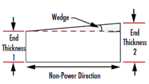
Illustration: wedge caused by end thickness difference of a cylindrical lens
Centration
The optical axis of the curved surface is parallel to the edges of the lens in an ideal cylindrical or acylindrical lens. Like the decenter in a spherical optic, the centration error of a cylinder lens is an angular deviation of the optical axis relative to the edges of the lens. This centration angle leads to the non-collinear of the optical and mechanical axes of the lens, thus the beam shift. If the edges of the lens are referred as a mounting position, this decenter can make optical alignment very difficult. The larger the diameter of a cylinder lens, the bigger the relevant edge thickness difference for a given centration angle.
Axial Twist
Axial twist refers to an angular shift between the cylindrical axis and the edges of a lens. Axial twist occurs when a powered surface of the cylindrical lens is rotated relative to its outer dimension, which may cause a rotation of the image about the optical plane. This is particularly problematic for applications when rectangular elements are secured by their outer dimensions. To handle the axial twist, we can realign the cylindrical axis by rotating the lens.
Applications
The most typical uses of cylindrical lenses in laser beam shaping are to produce a line, a light sheet, or to rectify an asymmetric beam. A narrow laser line is frequently needed for contemporary scientific techniques like Particle Image Velocimetry. Structured laser light is also a crucial tool for scanning, measurement, and alignment applications. Simply circularizing a diode’s elliptical output to produce a symmetric, collimated beam is another popular use.
Forming a Light Sheet
A light sheet refers to a beam that diverges in both the X and the Y axes. A rectangular field that is perpendicular to the optical axis and expands with increasing propagation distance is a feature of light sheets. A light sheet can also be defined as a laser line produced by a cylinder lens, even if the sheet is triangular and runs down the optical axis.
Two orthogonal convex and concave cylindrical lenses are needed to form a genuine laser light sheet with two diverging axes. A diverging sheet of light is produced by the combined action of both lenses, each of which operates on a distinct axis.
Circularizing a Beam
In the absence of collimating optics, the divergence of a laser diode will be asymmetrical. A spherical optic preserves the original asymmetry by acting on both axes simultaneously, making it impossible to create a circular collimated beam. However, treatment of each axis independently is made possible by an orthogonal pair of cylindrical lenses.
The ratio of the X and Y beam divergences should coincide with the focal lengths of the two cylindrical lenses to produce a symmetrical output beam. The diode is positioned at both lenses’ focal points, just like in regular collimation, and as a result, the distance between the lenses is equal to the difference in their focal lengths.
Due to the fact that divergence directly affects the system’s permissible length and the necessary lens sizes, laser diodes may have very strong divergence, which can make collimation difficult. Since the relative positions of each component are fixed because of their focal length, the maximum beam width (d) at each lens can be obtained through multiplying its focal length (f) by the divergence angle (θ) of the axis it is collimating. Then, each lens’s clear aperture needs to be greater than the matching maximum beam width. d=2f×tan(θ/2).
Thanks to the asymmetric nature of cylinder lenses, and the specialized manufacturing processes: specialized equipment, particular skills, Photonchina’s unique coordinate system to effectively reference features of a lens, it is important that above mentioned centration, wedge, and axial twist are specified and properly controlled, when our customers are considering buying cylindrical or acylindrical lenses.
About optical coating: coating and damage thresholds
About coating: these high performance multilayer AR coatings have an average reflectance of less than 0.5% (per surface) across the specified wavelength ranges. The central peak in each curve is less than 0.25%. These coatings provide good performance for angles of incidence (AOI) between 0° and 30° (0.5 NA). For optics intended to be used at large angles, Photonchina provides a custom coating optimized at a 45° angle of incidence; this custom coating is effective from 25° to 52°.
About Damage Thresholds: when choosing optics, it is critical to understand the Laser Induced Damage Threshold (LIDT) of the optics being used. The LIDT for an optic greatly depends on the type of laser you are using. Continuous wave (CW) lasers typically cause damage from thermal effects (absorption either in the coating or in the substrate). Pulsed lasers, on the other hand, often strip electrons from the lattice structure of an optic before causing thermal damage. Photonchina have to mention, however, the explanation here should be based on room temperature operation and optics in good condition (i.e., within scratch-dig spec, surface free of contamination, etc.), because dust or other particles on the surface of an optic can cause damage at lower thresholds.
The testing method of LIDT
First, a low power or low energy beam is directed to the optic under test. The optic is exposed in 10 locations to this laser beam for 30 seconds (CW) or for a number of pulses (pulse repetition frequency specified). After exposure, the optic is examined by a microscope (~100X magnification) for any visible damage. The number of locations that are damaged at a particular power/energy level is recorded. Next, the power/energy is either increased or decreased and the optic is exposed at 10 new locations. This process is repeated until damage is observed. The damage threshold is then assigned to be the highest power/energy that the optic can withstand without causing damage.
Continuous Wave and Long-Pulse Lasers
When an optic is damaged by a continuous wave (CW) laser, it is usually due to the melting of the surface as a result of absorbing the laser’s energy or damage to the optical coating (antireflection). Pulsed lasers with pulse lengths longer than 1 µs can be treated as CW lasers for LIDT discussions.
When pulse lengths are between 1 ns and 1 µs, laser-induced damage can occur either because of absorption or a dielectric breakdown (therefore, a user must check both CW and pulsed LIDT). Absorption is either due to an intrinsic property of the optic or due to surface irregularities; thus LIDT values are only valid for optics meeting or exceeding the surface quality specifications given by a manufacturer. While many optics can handle high power CW lasers, cemented (e.g., achromatic doublets) or highly absorptive (e.g., ND filters) optics tend to have lower CW damage thresholds. These lower thresholds are due to absorption or scattering in the cement or metal coating.
Pulsed lasers with high pulse repetition frequencies (PRF) may behave similarly to CW beams. Unfortunately, this is highly dependent on factors such as absorption and thermal diffusivity, so there is no reliable method for determining when a high PRF laser will damage an optic due to thermal effects. For beams with a high PRF both the average and peak powers must be compared to the equivalent CW power. Additionally, for highly transparent materials, there is little or no drop in the LIDT with increasing PRF.
In order to use the specified CW damage threshold of an optic, it is important to know the following:
- Wavelength of laser
- Beam diameter of beam (1/e2)
- Approximate intensity profile of beam (e.g., Gaussian)
- Linear power density of beam (total power divided by 1/e2 beam diameter)
Pulsed Lasers
Pulsed lasers usually induce a different type of damage to the optic than CW lasers. Pulsed lasers often do not heat the optic enough to damage it; instead, pulsed lasers produce strong electric fields capable of inducing dielectric breakdown in the material. However, it can be very difficult to compare the LIDT specification of an optic to the laser. There are multiple regimes in which a pulsed laser can damage an optic and this is based on the laser’s pulse length.
When comparing an LIDT specified for a pulsed laser to the laser, it is necessary to know the following:
- Wavelength of laser
- Energy density of beam (total energy divided by 1/e2 area)
- Pulse length of laser
- Pulse repetition frequency (prf) of laser
- Beam diameter of laser (1/e2 )
- Approximate intensity profile of beam (e.g., Gaussian)